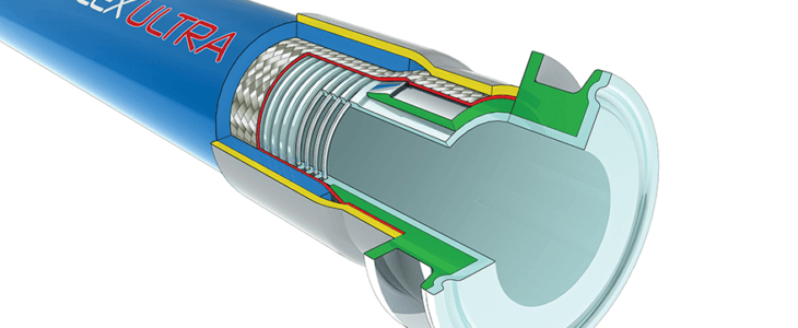
Bioflex Ultra Hose Design Options
Bioflex Ultra Hose Grades are made up by combining the Design Options, which are defined by 2 letters as shown below, and fully described in the linked sections.
For example, “Bioflex Ultra AS, PB, SG” defines a hose with an Antistatic PTFE liner (AS) and a Polypropylene braid (PB) and an outer Safegard (SG) spiral HDPE protection sleeve.
PTFE Liner Tube Options – GP (Natural PTFE) and AS (Antistatic PTFE)
Braid Options – TO (Tube Only, No Braid), SS (316 SS Wire), and PB (Polypropylene)
Rubber Cover Options – RC (Blue EPDM), BK (Black EPDM) and SI (Silicone Rubber)
External Protection Options – SR (Scuff Rings), SG (Safegard Spiral) and PC (SS Wire Coil)
Bioflex Ultra in Comparison with Convoluted PTFE Hose
Hygienic Cleanability – much better, due to no internal convolutions
Flow Rates – more than 2 x higher
Pressure Ratings – more than 1.5 x higher
Self Draining – excellent self draining with PTFE lined fittings
Non-Whistling – no whistling noise with gasses
Bioflex Ultra in Comparison with Conventional Smoothbore FEP, PFA or PTFE Lined Rubber Hose
No Adhesives – no toxic adhesives used in the Bioflex Ultra construction, eliminating the possibilities of Process Fluid contamination in service
Flexibility – much better flexibility
Internal Shape Control – no distortions in bore when flexed
Bioflex Ultra in Comparison with Silicone Rubber Hose
Hygienic Cleanability – much better, due to the non-stick PTFE Liner
Chemical Resistance – considerably improved, particularly to strong oxidising acids and bases
Temperature & Pressure Ratings – much higher temperature and pressure capability
Steam Resistance – permanently resistant to steam sterilising (unlike silicone hose, which has a limited life)
Bioflex Ultra GP, SS with a PTFE Lined Sanitary Triclover Fitting
Temperature vs Pressure
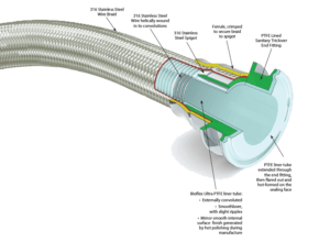
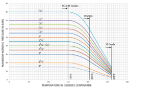
Due to its extremely strong construction, Bioflex Ultra has outstanding resistance to temperature and pressure, much higher than that of conventional convoluted PTFE lined hose.
Maximum Working Pressure (MWP) Variation with Temperature: MWP for SS grade hose, also for RC, BK and SI grades are as given in the graph, BUT only within the temperature range for the particular grade of hose, as given below:
Min/Max Operating Temperatures:
Bioflex Ultra GP or AS SS -73˚C to +260˚C
Bioflex Ultra GP or AS SS,RC & SS, BK -40˚C to +150˚C
Bioflex Ultra GP or AS SS, SI -73˚C to +204˚C
Bioflex Ultra GP or AS PB – MWPs for PB are as given in the graph up to 80˚C, then reduced by 50% between 80˚C and 100˚C (the maximum for PB).
Temperature vs Vacuum
All sizes and grades of Bioflex Ultra hose are usable at vacuum to -0.9bar up to 200˚C (100˚C for TO grades). Above this, the vacuum resistance should be reduced 2% for every degree above 200˚C (100˚C for TO grades).
Temperature & Maximum Working Pressure Graph for Bioflex Ultra
Flow Rates
In practice, flow rates will vary with hose flexing, fluid viscosity, end fitting design and other parameters, but Bioflex Ultra hose flow rates are always around 2 times better than convoluted PTFE hose, when comparing hose assemblies with PTFE lined (non bore-restricted) end fittings.
Bioflex Ultra Hose – Flow Rate Calculation
If it is required to determine the flow rate of a particular hose assembly, or if it is required to determine the pressure required to generate a certain flow rate, then this can sometimes be approximately calculated by the Bioflex Ultra supplier.
It should be noted that calculations can only be made for fluids with a viscosity equal to water, and for hose assemblies with PTFE lined end fittings (no bore restrictions at the ends of the hose).
The following information should be given to the supplier
To calculate the Flow Rate in Cubic Metres per Hour:
- Pressure in Bars at the Entry into the Hose Assembly – subtracted from – Pressure in Bars at the Exit from the Hose Assembly (to calculate Pressure Drop over the Hose Length).
- The hose configuration (roughly straight, or 33% Bends, or 66% Bends, or 100% Tightly Coiled)
OR To Calculate the Pressure Drop in bars over the length of the Hose Assembly:
- Required Flow Rate in Cubic Metres per Hour
- The hose configuration (roughly straight, or 33% Bends, or 66% Bends, or 100% Tightly Coiled)
SIZE, GRADES, BEND RADII & DIMENSIONS
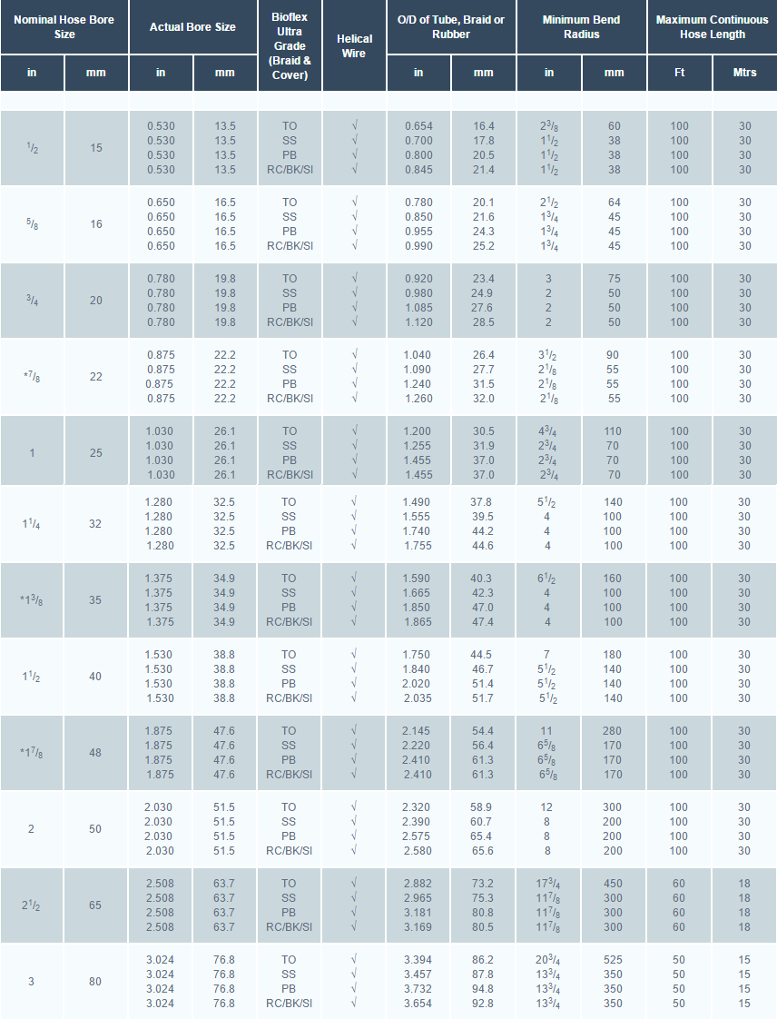
*The 7/8”, 13/8” and 17/8” hose sizes are only suitable for use with PTFE lined sanitary clamp (or triclover) end fittings and PTFE lined I-Line end fittings
SIZES, GRADES, PRESSURES & WEIGHTS
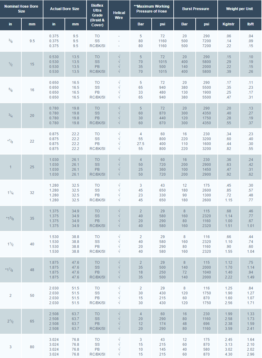
* The 7/8”, 13/8” and 17/8” hose sizes are only suitable for use with PTFE lined sanitary clamp (or triclover) end fittings and PTFE lined I-Line end fittings.
** The Maximum Working Pressure of a hose assembly is limited to the lowest of the MWP’s of either of the two end fittings, or of the hose itself as listed above. The MWP of the hose reduces as the operating temperature increases as specified in the Graph.
